
DIY Discharge Stick
Never attempt to discharge filter capacitors using a screwdriver! Direct dead-shorts cause dangerous arc flashes, pit metal chassis contacts, damage capacitor foils, and can detonate internal power supply rectifiers. Building and using a proper insulated discharge stick ensures a safe, spark-free discharge.
DIY Capacitor Discharge Stick: Construction Guide
Step-by-step instructions on building an insulated workbench capacitor discharge tool for safely bleeding high-voltage filter capacitors in valve amplifiers.
1. Required Materials & Components
All items should be high-voltage insulated and rated appropriately for high-voltage DC circuits (300V–600V DC):
| Component / Material | Recommended Specification | Function |
|---|---|---|
| Discharge Resistor | 10kΩ to 22kΩ, 5W to 10W Ceramic Wirewound | Limits discharge current and safely dissipates energy as heat. |
| Insulated Probe Shaft | Non-conductive PVC or fiberglass tubing / wooden dowel | Serves as the insulated handle keeping your hands clear of live chassis terminals. |
| Multimeter Probe Tip | 1x Rigid copper probe tip or heavy-duty multimeter needle | Provides a precise contact point to touch valve sockets or capacitor lugs. |
| Ground Lead & Clip | 18 AWG flexible silicone wire (~1m) + insulated alligator clip | Connects the discharge circuit firmly to the metal chassis ground. |
| Heat Shrink Tubing | Dual-wall adhesive-lined heat shrink tubing (6mm & 12mm) | Insulates all exposed solder joints and resistor leads. |
2. Assembly Process (Step-by-Step)
Step A: Prepare the Discharge Resistor
Take your 10kΩ 5W power resistor. Trim one lead down to roughly 15mm. Solder this trimmed lead directly to the rear metal collar of your probe tip. Ensure a smooth, mechanically solid solder connection.
Step B: Attach Ground Lead
Strip 10mm off one end of the 18 AWG ground wire. Wrap it securely around the remaining lead of the resistor and solder thoroughly. Solder the insulated alligator clip to the opposite end of the wire.
Step C: Insulate All Exposed Metal
Slide dual-wall adhesive-lined heat shrink tubing over the entire resistor assembly, extending past the solder joints. Shrink it using a heat gun until sealant squeezes out at the ends, leaving only 3mm of the probe tip exposed.
Step D: Mount Inside Probe Handle
Insert the insulated assembly into a hollow plastic probe tube or secure it to a rigid insulating handle. Pass the ground wire out through the rear end of the handle and apply stress relief strain control.
Discharge Tool Circuit Architecture
The power resistor sits inline between the insulated probe tip and the ground clip lead.
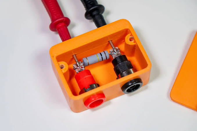
A 5W to 10W ceramic wirewound resistor provides safe energy absorption without melting.
3. Operating Protocol: How to Safely Bleed Capacitors
Standard Operating Procedure:
- Power Off & Unplug: Switch off the amplifier power and standby switches. Completely disconnect the AC power cord from the wall outlet.
- Attach Chassis Ground: Attach the insulated alligator clip to an unpainted section of the metal amplifier chassis ground.
- Touch Anode / Cap Positive: Using one hand only (keep your other hand in your pocket), touch the probe tip to Pin 1 or Pin 6 of a preamp valve socket, or directly to the positive terminal of the first reservoir capacitor.
- Hold for 10–15 Seconds: Hold the probe firm for 10 to 15 seconds while the ceramic resistor safely converts stored energy to harmless heat.
- Verify Zero Volts DC: Set your digital multimeter to DC Volts. Measure across the capacitor positive terminal to ground. Confirm the reading is **0.00V DC** before touching any internal wires.


